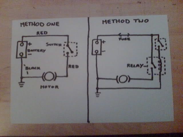
Anyway, I don't know how this diagram will come out on here - but here goes:
The first method is the way described above for a straight forward wiring circuit.

The second method is only slightly more complicated, but is much more suitable for low voltage - high current applications.
This way, the relay is designed to switch the higher currents and the switch is only to power the relay.
Both of these can be bought at any motorist type shop like: Halfords or McGanns and even some garages for a few quid.
This system is even used for switching the headlights on in your vehicle, amongst other things. It is also safer because of the lower currents needed at the initial switch point and all the heavy duty stuff is kept out of the passenger compartment - reducing the risk of fire.
You say the pump draws 8 amps - so a relay capable of switching about 10 - 15 amps would be ideal.
Hope I haven't bored you all to death with this?