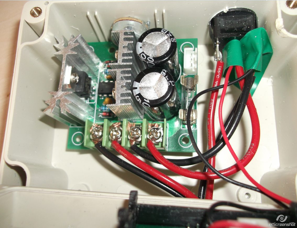
Here you go. I think it looks a bit confusing, but it's pretty straightforward. The meter wires are the thinner ones bottom right of the picture as you see it. You see the black one goes to the post on the far right (with the other negatives) and the red one goes to the middle post.
The red wire on the far left is power in post (from the battery) and if you attached it to this one, the meter would be on all the time, even when the pump was switched off.

It's a bit of a bodge job, 'cos that's the kind of person I am, I'm afraid. 
I can think of a few improvements for my next one though.
I wired one up, and done same as your diagram. I found it a bit of a pain putting two then three wires together on the switch terminal. Then it dawned on me, after the event (normal for me !! :-) ), the voltmeter wires can just go to the terminals on the switchboard itself (the two right hand ones), it'll be much easier this way.
Also the controller in my van today was flashing up "batt", still working ok, but still flashing up. It also showed a voltage of 12.4v. I brought the battery in to test this new controller out and the voltmeter on the controller i just made showed 12.7v . I tested the accuracy of this with a multimeter, and the multimeter showed 12.7V. I realise my van controller may need rewiring with good contacts, so the point i'm making is just them small voltmeters are accurate.
I'm very happy with the result, and just about to order a few more bits to make some more up , cheers Tosh !! :-)